You are here:
Fiber Optic Attenuators
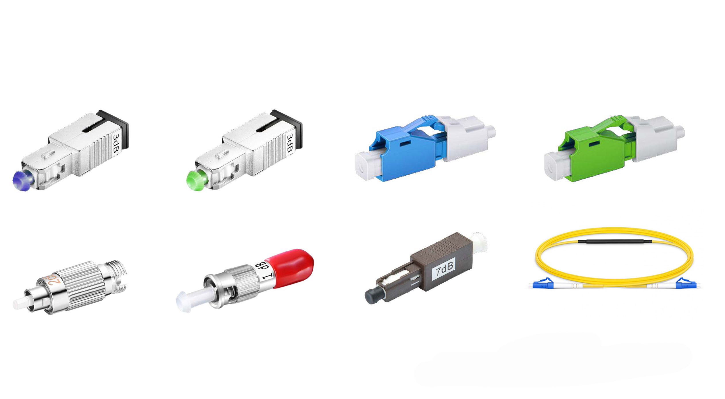
Table of Contents
- What are Fiber Optic Attenuators
- Fiber Optic Attenuator Package Types
- Working Theory of the Fiber Optic Attenuator
- Three Major Types of Fiber Optic Attenuator
- What is dB - Decibels (dB)
- Calculating the Attenuation Values with Attenuators
- Using Female to Male Fiber Optic Attenuators to Test Receiver Sensibility
What are fiber optic attenuators
Fiber optic attenuator, or named optical fiber attenuator, refers to a passive fiber optic component that is used in the fiber optic link to reduce the light power to a pre-set value (this value is often described as a certain dB). Fiber optic attenuators are generally used in single mode long distance transmissions (there are indeed multimode types fiber optic attenuators for some applications), by reducing the light power via the attenuator, it helps avoid too high overload at the receiving end.
The pre-set value is usually
0dB,1dB,2dB,3dB,4dB,5dB,6dB,7dB,8dB,9dB,10dB,11dB,12dB,13dB,14dB,15dB,16dB,17dB,18dB,19dB,20dB,21dB,22dB,23dB,24dB,25dB,26dB,27dB,28dB,29dB,30dB
and other custom values. dB is also one of the
commonly used terms to describe the quality of a
certain fiber optic signal. dB is short for decibel,
which was originally used to measure the strength of
sound. dB means 1/10 of a bel. For a fiber optic
attenuator, the most important terms to describe it is
its connector type, such as LC/UPC, LC/APC, SC/UPC,
SC/APC, FC/UPC, FC/APC, ST/UPC, ST/APC, MU/UPC, MU/APC
and its corresponding dB level.
Fiber optic attenuator package types
There are a few different types of fiber optic attenuators based on its package, including the bulkhead attenuator, inline fiber optic attenuator, hand-held fiber optic attenuator, variable fiber optic attenuator.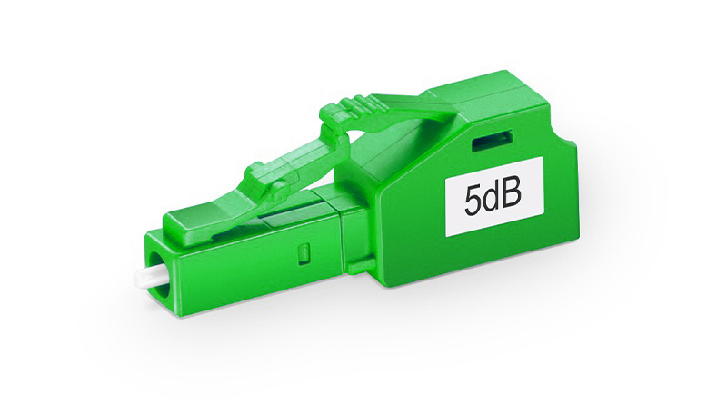
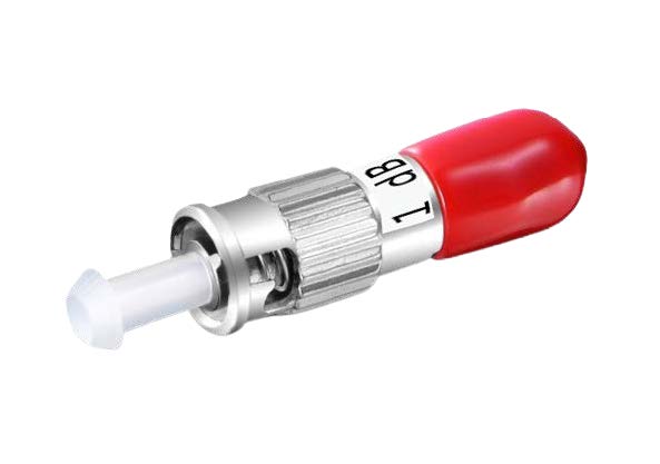
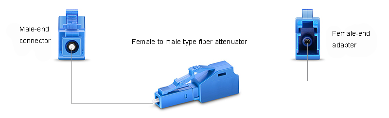
Bulkhead fiber optic attenuator is also named female to male attenuator, it is a small size component looks like a female to male fiber optic adapter, when you plug the connector from the female side, the light power goes through the attenuator will be reduced, it is totally plug and play, simple to use. Because they have unchanging level of attenuation, they are also called fixed value fiber optic attenuator.
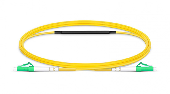
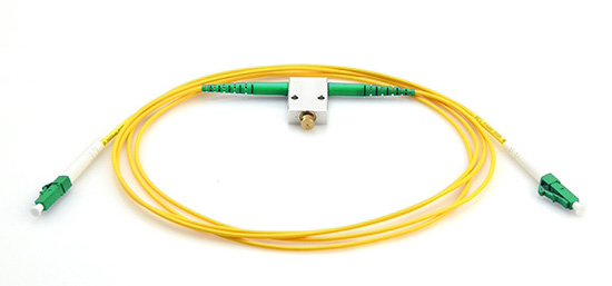
The other fixed value attenuator is a patch cord type, which is called inline fiber optic attenuator. These inline fiber optic attenuators are generally used to link from the rack / patch panel interface to the other equipment. It has pre-defined fixed attenuation value, and it has connectors at each end of the cable. Inline fiber optic attenuators can be various length which is made according to your needs.
Working theory of the fiber optic attenuator
Based on the different working theories, we will explain the commonly used attenuator types which are fixed attenuation value attenuators, stepwise variable fiber optic attenuators, and continuously variable optical fiber attenuators.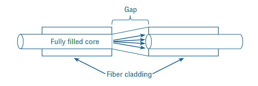
GAP-loss attenuator is a typical inline fiber optic attenuator. It is usually placed very close to the transmitter. Only in this way can it achieve the preset attenuation value more accurately. The farther it is placed from the transmitter side, the less accurate it will work.
We have drawn a working principle illustration picture
of the gap loss attenuator. As can be seen from the
picture, the gap-loss attenuator artificially creates
a gap in the fiber, so that when light passes through
the gap from one fiber to another fiber, Due to the
existence of the gap and the divergence of light, the
purpose of attenuation is achieved. The gap loss
attenuator is not recommended if you want to achieve
precise attenuation at the far end of the transmitter.
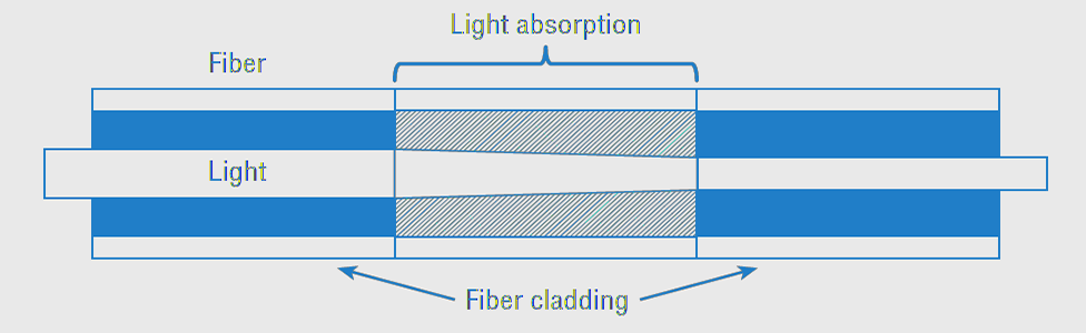
Absorptive Principle is a popular way to make fiber optic attenuators. Traditionally, it is the low-attenuation, high-quality fiber that makes long-distance fiber-optic communication possible. But when making attenuators, we can instead use imperfect fibers to achieve the desired attenuation. We can use a piece of material in the fiber attenuator to absorb the energy of the fiber. When the light passes through, the material absorbs the energy of the fiber and converts it into heat, so that the energy of the light is reduced, this is how the absorptive attenuators work.
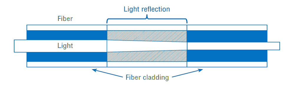
Light scattering is one of the main causes of light attenuation in optical communication, and this characteristic is also used in the manufacture of optical fiber attenuators. In this type of attenuator, one uses an attenuating material so that only a portion of the light that matches one's pre-designed values can propagate through it, so the total amount of light that passes is reduced to achieve attenuation.
Three major types of fiber optic attenuator
Fixed fiber attenuators are available in LC, SC, ST, FC and MU styles with APC and UPC polishes. Usually, attenuators are not needed for multimode systems because multimode source VCSELs rarely have enough power output to saturate the receiver. Instead, single-mode systems, especially short links, are often too powerful and require attenuators.
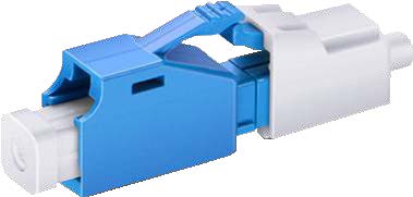
LC/UPC female to male fiber attenuator
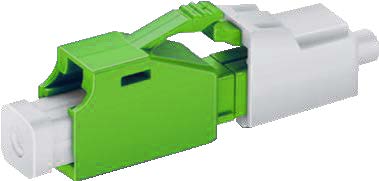
LC/APC female to male fiber attenuator
SC/UPC female to male fiber attenuator
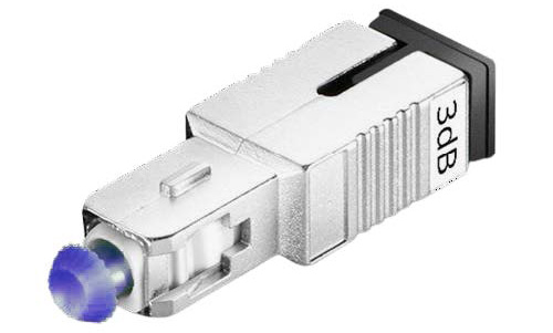
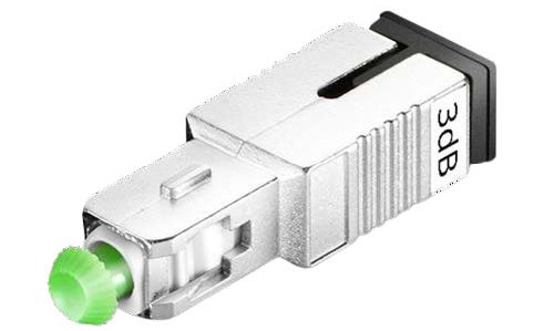
SC/APC female to male fiber attenuator
MU/UPC female to male fiber attenuator
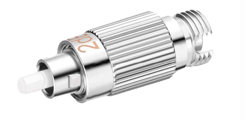
FC female to male fiber attenuator
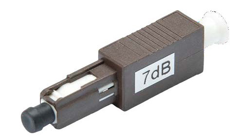
ST female to male fiber attenuator
Therefore, fixed fiber attenuators are usually of the single-mode type. The most commonly used types are LC single-mode female-to-female and female-to-male fixed fiber optic attenuators and SC single-mode female-to-female and female-to-male fixed fiber optic attenuators. Different from the common female-to-male type mentioned above, the female-to-female fixed fiber optic attenuator has a female fiber optic adapter at both ends, so it is also called a fiber optic adapter type attenuator. They can be used as adapters and attenuators at the same time.
LC/APC female to male fiber attenuator
SC/UPC female to male fiber attenuator
SC/APC female to male fiber attenuator
MU/UPC female to male fiber attenuator
FC female to male fiber attenuator
ST female to male fiber attenuator
Therefore, fixed fiber attenuators are usually of the single-mode type. The most commonly used types are LC single-mode female-to-female and female-to-male fixed fiber optic attenuators and SC single-mode female-to-female and female-to-male fixed fiber optic attenuators. Different from the common female-to-male type mentioned above, the female-to-female fixed fiber optic attenuator has a female fiber optic adapter at both ends, so it is also called a fiber optic adapter type attenuator. They can be used as adapters and attenuators at the same time.
The step variable attenuator has a real-time variable fiber attenuation value, which can range from 0.1dB, 0.5dB, 1dB to a larger desired range. The step variable fiber optic attenuator can be used when there are multiple light sources. For example, if you have 4 inputs light source, you may need to adjust the attenuation of the signal for each input. In addition, the step variable attenuator can also be used to adjust the output signal. At this time, your input signal is stable, but the output signal needs to be adjusted. In either case, before choosing to use attenuators, it is necessary to confirm the performance parameters of the inputs, outputs and equipment.
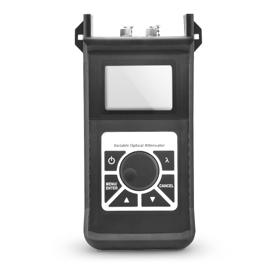
The Variable Fiber Optic Attenuator is widely used in optical communication, and its primary function is to reduce or control the optical signal. The most fundamental characteristic of an optical network should be adjustable, especially with the application of DWDM transmission system and EDFA in optical communication. For the applications where the input and/or the output need continually adjust and without interruption of the transmission, the VOA (variable optical attenuator or variable fiber optic attenuator) is an indispensable key device. Typical variable fiber optic attenuators in the market include manually variable fiber optic attenuators and electronic variable fiber optic attenuators, these variable fiber optic attenuators work with single mode, multimode and PM fibers.
What is dB - Decibels (dB)
In the process from the light passing through the transmitting end to the receiving end, the signal will be attenuated, that is to say, the light will lose some energy in the process. This loss of energy can be caused by many reasons, such as insufficiently pure fibers, damaged fibers, or gaps at the connections between components, etc.The
receiving end of the fiber needs enough energy to
work, and we need to be able to measure the total
energy loss of the light from the transmitting end to
the receiving end. Also, being able to know and find
out where and how much energy the light is losing
primarily in the link is critical to our
troubleshooting.
In optical communication, we introduce the unit dB to
describe the change of optical signal. For example, we
often see how many dB is the fiber attenuator, and how
many dB is the insertion loss of the fiber optic patch
cord. what is dB? The full writing of dB is decibel,
deci means one tenth in English (actually in Latin).
So this unit dB was originally from the unit Bel.
However, because the energy difference required to
achieve a numerical comparison of a bel is usually
relatively large and is not commonly used in fiber
optics, one-tenth of a bel, that is, the unit decibel,
is more commonly used. The unit Bel is to commemorate
Alexander Graham Bell (March 3, 1847 - August 2, 1922)
who was an American inventor and entrepreneur. He
patented the world's first usable telephone, created
the Bell Telephone Company (predecessor of AT&T).
The unit dB was originally used to measure the sound
heard by the human ear.
In fact, it means that when you encounter two energies
(signals), dB is a unit of representation we use to
express the difference between these two energies. It
is not an independent absolute unit (such as Volt,
Ampere, etc.) itself. The appearance of the dB unit
means that there are two units of energy (or signals)
of the same nature being compared.
Calculating dB Power Loss and Power Gain
In optical fiber communication, dB is mainly used to describe optical power, that is, signal power. An optical power meter is a special device used to test optical power. With the maturity of technology and components, the price of optical power meters has been reduced to a much lower level than before.
In the 1960s, the initial goal was to achieve a fiber
attenuation of 20dB per kilometer, so that optical
fiber communication could become a reality from
theory. Actually, 20dB per kilometer attenuation is a
very large energy loss, it means that almost 99% of
the energy is lost in this transmission process.
Fiber
attenuation in today's era has reached such low levels
that fiber amplifiers are no longer required in most
cases. In optical fiber communication, we use the unit
of dB to calculate the optical loss in the entire
link. In the case of using a fiber amplifier, we can
also use dB to calculate the signal power gain
provided by the fiber amplifier.
We
use the following equation to accurately calculate the
dB value of the loss or gain in optical power: dB=
10*Log10(Pout/Pin)
The
logarithm base 10 of a number is its logarithm to the
base of 10 where Log (1) = 0.
Use this equation to calculate loss in dB
Let's illustrate how to use this equation to calculate the loss of a fiber optic link. If the transmitter sends 10uW into the link and at the receiver end we get 4uW. Using the above equation, we can getdB=
10*Log10 (4/10)
dB=
10*Log10 0.3
Loss
=-3.98dB
From
the above calculation result we get a negative value,
which means it is a loss. When we use it to express
loss, we remove the preceding minus sign. Therefore,
we say that the optical loss is 3.98dB.
Use this equation to calculate gain in dB
Through this equation, we can also calculate the gain of the fiber amplifier. Usually, it is not necessary to use the amplifier in the fiber link, because the attenuation caused by the modern fiber is low enough, but when the transmission distance is relatively long, there is still fiber amplifiers may be required. Let's do a simple calculation with an example, assuming that the amplifier input power is 1uW and the output power is 20uW.dB=
10*Log10 (20/1)
dB=
10*Log10 20
Gain
=13.01dB
Use this equation to calculate power if we already know dB value
We can also transform the dB equation so that when we know the dB value, we can know the ratio of input power to output power, or their exact values.Because
dB=
10*Log10(Pout/Pin)
then
(Pout/Pin)=
antilog (dB/10)
Let's take an example to illustrate the usage of this
equation. We need to remember that dB is the ratio of
output power to input power. If we know that the loss
of the fiber is 3dB.
(Pout/Pin)=
antilog (dB/10)
(Pout/Pin)=
antilog (-3/10)
(Pout/Pin)=
antilog -0.3
(Pout/Pin)=
0.501
If
one value of input power and output power is known,
and the dB value is known, we can calculate the other
value. We continue the above equation calculation, if
we already know that the input power is 12mW, then we
calculate the input power:
(Pout/Pin)=0.501
Pout=
0.501* Pin
Pout=
0.501* 12mW
Pout=
6.01mW
Understanding the dB in percentages
It is important to keep this in mind when dB is used to measure the gain or loss of a signal, it describes a ratio relative to the original signal. The dB value allows us to intuitively know the rate of change of the signal. For example, 0.1dB means about 98% of the signal power remaining. And if the dB value reaches 3, then it means that only 50% of the signal power remains.
In actual work, 3dB and 10dB are two values to keep in
mind, because if the loss value is 3dB, it means that
the signal is attenuated by half, and the loss value
of 10dB means that the signal is attenuated by 90%. If
the value of gain is 3dB, it means that the signal
strength is twice as high as before, and if the value
of gain is 10dB, it means that the signal strength is
10 times as strong as before. So 3dB and 10dB are
figures with more typical reference meanings.
This
relationship is not linear but logarithmic, which
means that if the dB value of loss increases by 10dB,
the signal will be attenuated by one-half of the
previous value. The gain's dB value increases by 10dB
each time, the signal will be enhanced to 10 times of
the original.
The Rule of Thumb to use dB
In addition to the two values of 3dB and 10dB that we have mentioned before, we often use the value of 7dB in our work. 7dB loss means 80% signal attenuation, and 7dB gain means signal strength is 5 times stronger than before. The 3dB, 7dB and 10dB are the rule of thumb of to use dB in practical work. We can perform quick and easy calculations using these three values.Below
we explain how to use these rules of thumb. Because dB
can be added and subtracted algebraically, You can use
a combination of dB values to calculate total gain or
total loss. For example, we know that the input of the
fiber optic amplifier is 10uW and its gain is 13dB,
then we first use the 10dB rule, multiply 10uW by 10.
Then we can use the 3dB rule, multiply the result we
just got by 2. This is what we finally get the
remaining output value.
Pout=
10uW x 10
Pout=
100uW
Pout=
100uW x 2
Pout=
200uW
So
the output of the amplifier is 200uW.
Of
course, these rules of thumb do not apply to all
situations. For example, when the gain of the
amplifier is 18dB, we cannot use these rules to get
accurate results. But we can still estimate an
approximate range, because according to the example we
gave above, we can calculate through the rules of
thumb that a gain of 17dB corresponds to 500uW, and
20dB corresponds to 1mW, so we can still estimate that
18dB The corresponding output value should be between
500uW and 1mW.
Absolute Power and dBm
By itself, dB is just a relative number, it only has meaning when referenced to a known input or output power. But sometimes we still need to know the absolute value, in this case, the dB is referenced to 1mW (milliwatt), we add a lowercase m or mW after dB. 1mW is 0dBm.When
using dBm as the unit, power levels below 1mW are
negative and power levels above 1mW are positive.
-3dBm means that the signal attenuation of 1mW is half
of the previous one, which is 500uW. And 3dBm means
that the signal of 1mW is enhanced by 2 times of the
previous one, which is 2mW.
We
use an equation to express the relationship between
power and dBm, through which we can also convert
between them.
dBm = 10Log10*(P/1mW)
If
you compare this equation with the previous equation
for calculating dB, you will find that they are very
similar, the only difference is that the input power
is a fixed value of 1mW. Using this equation, we can
know the dBm value Calculate the optical power, if the
optical power is known, the value of dBm can also be
calculated.
To
calculate optical power:
Assuming the power meter gets -6dBm, the use the dBm
equation, we can get:
-6
= 10Log10*(P/1mW)
-0.6=
Log10*(P/1mW)
0.2512=(P/1mW)
P=
0.2512* 1mW
P=0.2512mW
To
Calculate the dBm value:
For example the power value is 20uW. Then we can use
the dBm equation:
dBm
=10Log10*(P/1mW)
dBm
=10Log10*(20uW/1mW)
dBm
=10Log10 (0.02)
dBm
=10x -1.699
dBm
= -16.99
the power value is -16.99dBm, roughly 17dBm.
When using the dBm unit, the dBm value above 1mW is a
positive number, the dBm value below 1mW is a negative
number, and the dBm value corresponding to 1mW is 0.
The
units dB and dBm are often confusing. We just need to
remember that db describes loss and gain level, and
dBm describes absolute power. In fact, if the loss is
3dBm, what you describe is that the loss of optical
power in Watts is 2mW. means that the fiber link has
half the signal attenuation (half the energy is lost
from the initial state)
dB is used in more than fiber optic filed
The use of the unit dB is not only in the field of optical communication, as we said before, it was originally a unit used to express sound. dB is also used for electrical transmission performance, no matter what kind of field, the calculation method of dB is the equation we listed earlier. Also, it is important to remember that dB is a ratio, and the dB value depends on the ratio of input power to output power. Understanding the meaning of dB helps us compare the performance parameters of different products. For example, we get two identical cables, but their attenuation parameters are 16dB and 22dB. Generally speaking, we all know that the smaller the attenuation, the better. Of course, the 16dB cable will be a better choice. But how much better is it than 22dB? According to the knowledge of dB we have learned and the method of calculating dB, we will accurately understand that although the two cables appear to have only a difference of 6dB attenuation value, these 6 dB bring 75% more of the attenuation on the 22dB cable.Calculating the attenuation values with attenuators
There are so many types of optical fiber attenuators. When choosing, we not only need to consider the application scenario and the type of optical fiber connector, but also need to calculate the required optical attenuation value.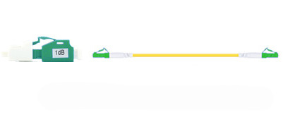
The type of connector is obvious, here we give an example to illustrate how to simply calculate the attenuation value of the required attenuator. For example, we know that the maximum endurance of the fiber-optic receiver is -7dBm. If the received optical power is greater than this value, then the receiver will be overloaded. At the same time, we know that the output power of the transmitter is 4dBm, and the difference between the transmitter and the receiver is 4dBm. The total attenuation of the fiber and the entire link is already 6dB, so we can list a formula:
Transmitter side power = 4dBm
Receiver side max power = -7dBm
Fiber
total loss = 6dBm
So
the max attenuation you may need is:
Receiver side max power+ Transmitter side power- Fiber
total loss
In
this example, it is -7dBm+6dB-4dBm= -5dB
It
can be seen from this that we will need a 5dB fiber
attenuator. Of course, it is possible that a fiber
attenuator with a larger attenuation value may also
work, as long as it does not cause excessive
attenuation and affect signal transmission.
Using female to male fiber optic attenuators to test receiver sensibility
The fiber optic receiver works best when the input power it receives is in a suitable range. We need to test whether the fiber optic receiver can work optimally at the lowest input power indicated on the data sheet. We can use the female to male fiber optic attenuator to test in a few simple steps.
The first step is to use the optical power meter to
calculate the output power of the optical fiber
transmitter. What we need to pay attention to is that
the transmitter and receiver used for testing need to
be of the same type. This means that we should avoid
using fast ethernet for transmission to match the
receiving end of gigabit ethernet. We already know
that for a specific network standard, the optical
fiber industry has a clearly defined range for the
power of the transmitting end and the receiving end.
In the second step, we connect the optical fiber
transmitter and receiver, and we adjust the power of
the transmitter to the maximum, because we want to
test whether the receiver can work well under the
minimum input power indicated by the equipment
manufacturer's data sheet, we need to find out the
value of this minimum input power.
The
third step is to calculate the required fiber
attenuation value and use a suitable female to male
fiber optic attenuator. For example, we know that the
power of the transmitter is -18dBm, and the minimum
power required by the receiver is -34dBm, then we can
calculate the required power The attenuation value of
is their difference, which is 17dB. We choose a
suitable 17dB optical fiber attenuator and place it in
the optical fiber link before the receiving end, and
restart the receiving end. If the receiver works fine
after rebooting, then it complies with the standards
indicated in the data sheet.
Purchase with confidence
Get a quick quote
Please use this� Contact Form or write to [email protected], we will reply as soon as possible.
Products News and Events
- Direct support and sales of the compatible transceivers: Compatible Transceivers
- Drop indoor cables, fast connector, terminal boxes and more:FTTH Products
More about Fiber Cables
- Insertion loss vs return loss�
- Plenum fiber optic cable
- Riser fiber optic cable
- Rohs fiber optic patch cable
- Simplex Vs duplex
- Single mode Vs multi mode
- LSZH fiber patch cord
- PC,UPC,APC
- 50/125 multimode fiber
- 62.5/125 multimode fiber
- 9/125 single mode fiber
- OM1 fiber cables
- OM2
fiber cables
- OM3 fiber cables
- OM4 fiber cables
- OS1 fiber cables
- Bend Insensitive Patch Cord
- Fiber Optic Connection
- Fiber Optic Termination
Fiber cable assemblies
Transceiver and converter
| Compatible Transceivers |
| Transceiver Cables |
| 100G QSFP28 |
| 40G QSFP |
| 25G SFP28 |
| 10G SFP+ |
| 1G SFP |
| XFP Transceivers |
| Fiber Video Transceiver |
| Fiber Optic Converter |
| 1X9 Fiber Optic Transceiver |
Testers and tools
| Fiber Optic Test Equipment |
| Fiber Optic Tool Kits |
Huihong TechnologiesAdd:6F,1st Bldg,ZYT industrial park, Shiyan area,Shenzhen,ChinaEmail:[email protected] Tel: 86.755.83053246 Fax:86.755.83464223 |
Fiber Optic Quick Guide |
News and ExhibitionsCompany news and exhibitions schedules for
this year and next year. click
here for details . |
Fiber Optic Applications
|
Customer Support
|
Copyright � 1998 - 2015.
China fiber optic manufacturer and china fiber optic cable
supplier,fiber optic transceiver manufacturer.


